The K40 Laser is probably one of the most popular, widely used desktop CO2 lasers on the market. Its price-point gives people the ability to enter the hobby world of laser engraving and cutting without breaking the bank.
Understandably, with a low price-point, there must be some trade-offs, one notably the k40 laser control board. We're talking about the M2 Nano control board that comes from factory with many of these units (some units come with upgraded control boards at a higher cost, but typically the M2 Nano is included).
In order to truly harness the capabilities of your K40 laser, there are a series of modifications that can be made to your unit that will unleash the beast, so to speak.
From Air Assist, more adequate ventilation, variable height bed, to upgrading the whole control board, these mods are widely documented and heavily supported by the K40 Laser community.
This writeup is no where near complete, however I've listed in dot form the steps of upgrading my K40 control board to an Arduino Mega 2560 with RAMPS 1.4 shield. Yes, typically a RAMPS 1.4 shield/board is destined for a 3d printer running Marlin, however it is also fully compatible with GRBL and runs this laser unit like a dream. Why did I chose RAMPS 1.4 shield? Simply speaking - I had one laying in a box that I purchased a few years ago to build another 3d printer, and subsequently didn't need it for the project.
So now, I've truly unleashed the power of my K40 laser, which now allows me to use Lightburn to interface (Lightburn is an extremely powerful Laser control software package, far more superior and usable to that of the standard K40 software (K40 Whisperer and MeerK40t). Now I am in no way 'bashing' these two pieces of software, but they simply lack the power and development backing than that of Lightburn.
DISCLAIMER: I am in no way responsible for any injury, death, property destruction, fires, or any other outcomes that may come from using this guide. If you use common sense and always think safety first, you should find your upgrade/conversion to go as smoothly as possible, in the safest manner possible.
DOWNLOADS
K40 Ramps 1.4 Firmware:
Download Here
K40 GRBL Settings File (load in lightburn):
UPDATED 31st January 2023
Download Here
K40 Ramps 1.4 Firmware Source:
Download Here
RAMPS Electrical Connection Diagram/Schematics
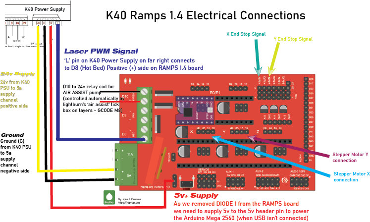
K40 Conversion to RAMPS 1.4 (Arduino Mega 2560 Shield) & GRBL
PHASE 1 - Arduino Mega 2560 & RAMPS 1.4 Setup
- Because the K40 runs at 24v, ie, the stepper motors also utilise 24v, your RAMPS board needs modifying. Remove DIODE 1 (as indicated below) and the 16v fuse, tie the fuse wires together with solid wire, OR replace with a car auto fuse. See diagram below.
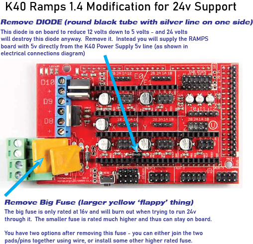
- Setup RAMPS board, stepper (stepping) jumpers, stepper drivers.
- Flash RAMPS Arduino Mega Board with K40 Firmware for RAMPS 1.4 (Provided on my website as precompiled hex, and source code). Once flashed, power it up via USB, connect to it with lightburn and import the default K40 GRBL settings (as will be provided on my website).
- On your existing K40 (or another laser) cut a base mount plate for the RAMPS board to mount into your K40 (SVG file supplied on my website)
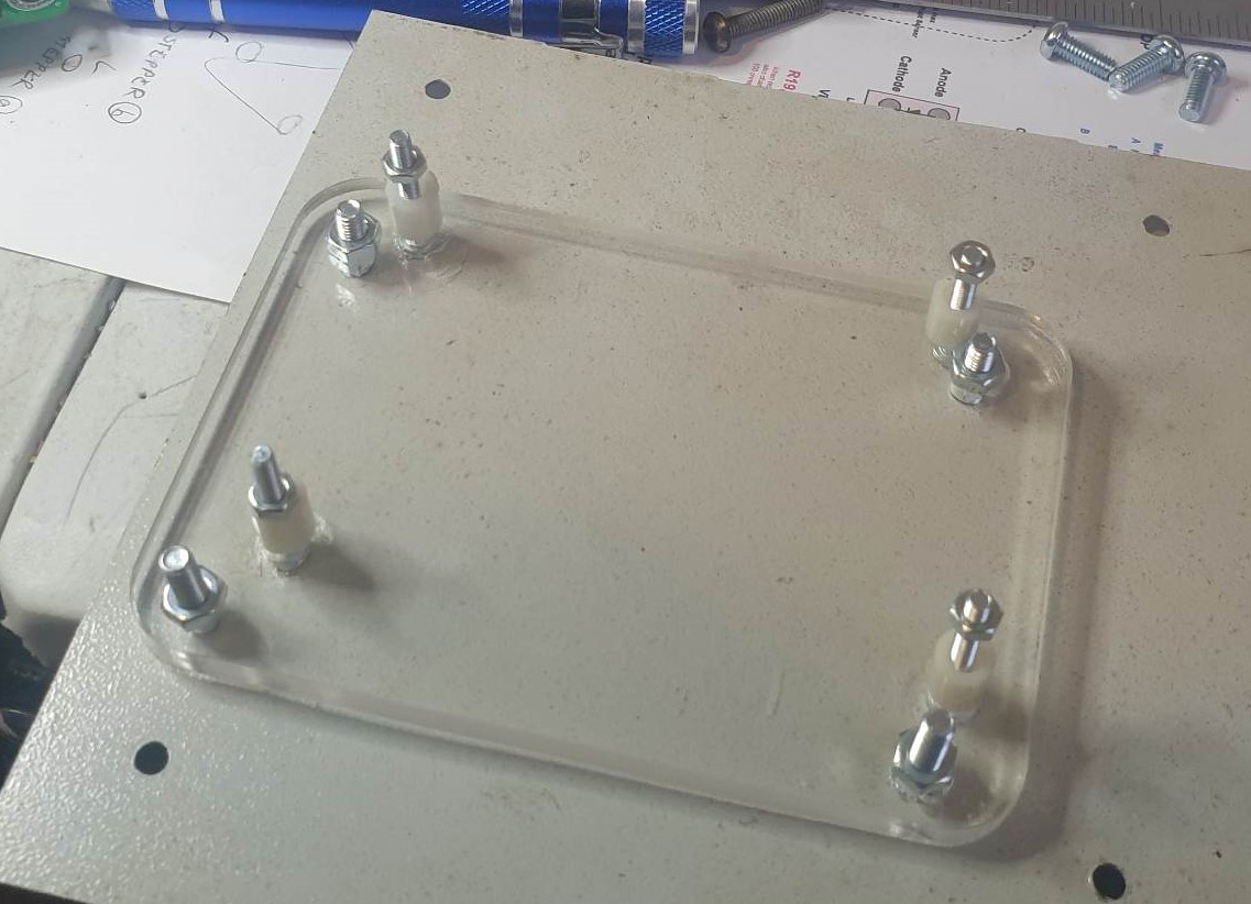
- Unplug K40 from all power sources.
- Remove M2 Nano board from your K40.
- Install a 2 core cable for 24v and GND power from K40 Power Supply to RAMPS 1.4 low amp power supply circuit (will be indicated on diagram).
- Because
the 5V diode was removed from the RAMPS 1.4 board (?D1), we also need to run a
5V line from the K40 Power Supply to the 5V+ dupont header on the RAMPS 1.4
board (will be indicated on diagram).
PHASE 2a – OPTICAL END STOPS (If your K40 uses Optical end stops – do this)
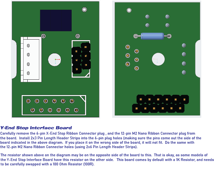
Y Board Pinout Diagram for the 12-pin Ribbon Plug/Cable - important: Take note of the side and orientation of the plug, ensure you match the correct sides and therefore the correct pins!
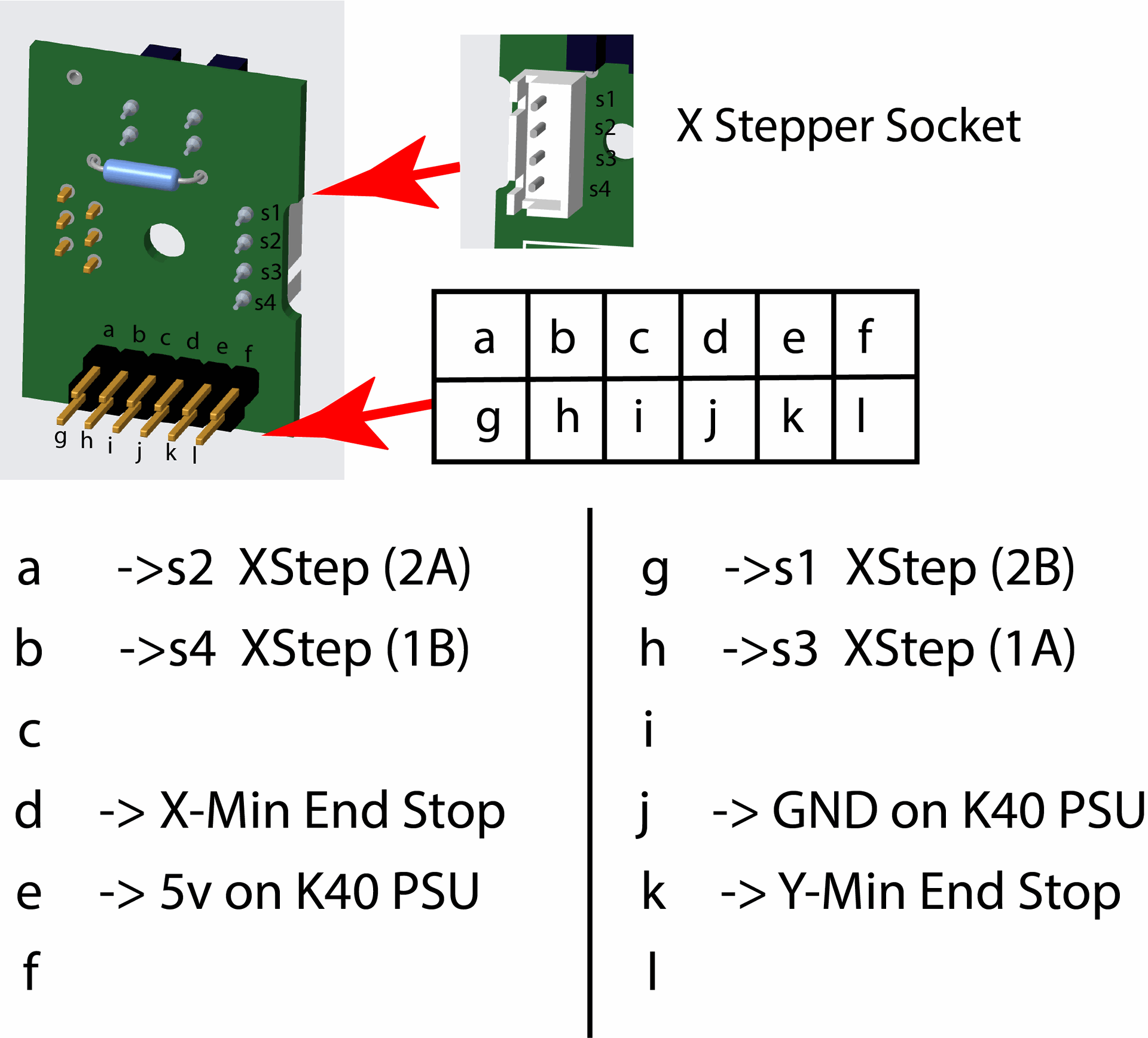
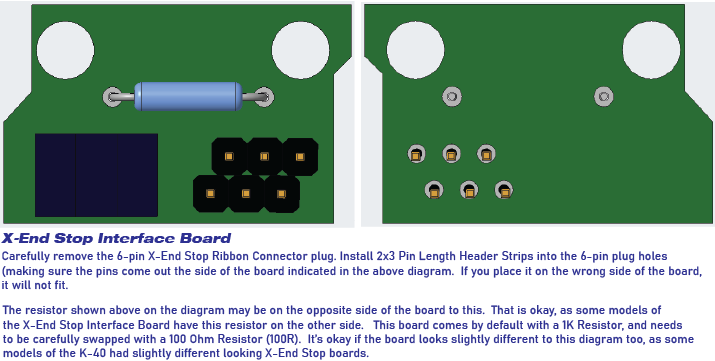
- If your K40 has the optical end stops, we need to remove the X and Y end stop daughter boards from the gantry (very simple, a few screws). The Y end stop board for example, is the board that the ribbon from the old M2 Nano board runs to. (will be indicated on diagram/photo).
- We need to modify both of these boards. It is super easy.
- Remove the 1Kohm resistor and replace with a 100Ohm resistor on both boards (this controls the power to the optical sensor’s LED) and the 1Kohm resistor doesn’t allow for the RAMPS board to reliably read the optical status. 100Ohm resistor fixes this. (will be indicated on diagram and photos)
- Carefully remove the large ribbon connector socket from the Y board. It’s relatively simple with basic soldering iron, solder sucker or solder wick. Just don’t rip the pads off the board. In place of this socket, we will install these things
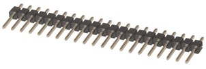
- ABOVE: (40 Pin Header Terminal Strip from Jaycar - $1.10, we just cut two ‘6 pin’ lengths to replace the 12 pin socket on the Y board – will be shown in diagram). Make sure you install them on the correct side of the board (as will be indicated in my diagram).
- Then, we carefully remove the two 6-pin ribbon connector sockets – one from the Y board, and one from the X board (which connects the X optical sensor to the Y board). We also replace these two sockets with 2 ‘3 pin’ lengths of the Header Terminal Strip. (will be shown in diagram). Make sure these header pins are also installed on the correct side of the X and Y boards as will be indicated in my diagram, otherwise the board won’t fit back in place!).
- Now,
the two 6-pin connector sockets, once they have the terminal strip installed –
we need to run 6* dupont wires from each of the header pins on the Y board to the
corresponding header pin on the X board.
(*check for redundant cables, some may be N/c, will update accordingly). This will be shown in a diagram, super easy.
PHASE 2b – MECHANICAL END STOPS (If your K40 uses mechanical end stops – do this)
- If your K40 uses mechanical end stops, we don’t need to remove the ribbon connector from the Y board, we just disconnect the ribbon cable (the big one that went from the Y board to the M2 Nano), and discard the ribbon – we wont be using it.
- At the time of writing this draft, I haven’t yet modified a k40 with the mechanical end stops, but they’re simply switches. Just need to make sure we have a cable running from the end stop switches that will properly route through the machine and over to the RAMPS board .. I will look more into this and edit, but do not worry, it will be very simple.
PHASE 3 – Wiring from the X/Y gantry to the RAMPS board
- We need to make a wiring harness that will contain eight wires, long enough to reach from the Y board, through the front channel of the K40 and over to the RAMPS board (this basically replaces the old flat ribbon cable). I used RJ45 (network) cable. But I would highly recommend some type of 8 core shielded wire to stop any unwanted ‘noise’). On each end of the harness, we just need connectors that will fit onto the Terminal Strip header pins. I used 4 of these cut in half -
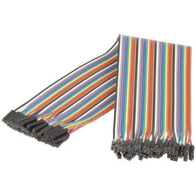
- ABOVE: 150mm Socket to Socket Jumper Leads - 40 Pieces $6.95 (jaycar) part number WC6026. Simply cut 4 of these in half, leaving them connected to each other, and terminate your 8-core wire on each end with the same colours (as will be shown in my diagram). BEFORE you terminate these wires, check the next step – because you may want to terminate 4 of these wires with a stepper motor board plug instead, just for easy visualization).
- Once this harness is created, plug it in to the pins as indicated by my diagram on the Y board 12-pin header you made. On the other end of the cable, it should be in the control box area where the RAMPS board is. The wires will plug into the RAMPS board as shown in my diagram, but the gist is :- 4 wires are for the X axis stepper motor. You can either glue the 4 connector wires together to create a 4-pin stepper plug to plug into the ‘X Stepper’ port on the RAMPS board, OR if you really wanted to, you could instead terminate these 4 wires separately with a stepper motor plug.
- If you have optical end stops, 1 of the wires goes to your 5V power supply line from your K40 power supply, there’s also a ground wire, and two signal wires (one for X and one for Y end stop). The X signal wire will plug into the X-min plug on the RAMPS board (as will be shown in my diagram), and likewise, the Y signal wire will plug into the Y-min plug on the RAMPS board.
- If you have mechanical end stops, as I am unsure as of writing, I need to check this out, however the stepper motor wiring will be the same, 4 wires will go to the ‘X Stepper’ port on the RAMPS board, there may be a 5v power line that goes over to the mechanical switches, then each mechanical switch will have a signal wire coming from it that will run respectively to X and Y min plugs on the RAMPS board (will update this as I research).
PHASE 4 – Testing End Stops
- Plug in your laser, making sure the LASER button is disabled – We don’t need any stray laser beams at this stage. We just need to check end stops and mechanical movements etc.
- I used software called ‘Candle’ to test my end stops, simply because it shows in real time when the end stops have been activated, but you can also use Lightburn – see below.
- Note – for this testing, you may want to turn off the ‘stepper motor hold’ functionality so that you can move the gantry around manually to check the end stop status. To do this, you need to change the GRBL setting ‘$1’ to a lower value, say 25. The value I’ve set in the K40 default settings is ‘255’ and it should be changed back to this after testing the end stops. This tells the stepper motor drivers to ‘lock’ or ‘hold’ the stepper motors in their current location, so that they can’t be moved manually.
- You can set GRBL settings by sending simple commands through the console in any connected software, for example $1=25 will change this value. You can restore this value by sending $1=255 after testing.
- CANDLE – Connect to the board using CANDLE software. Power on the K40. Watch the ‘status’ panel in Candle software while you move the gantry to the minimum (home) position on the X axis, then the Y axis, do them separately at first. You should see P: X, and P: Y displayed in the Candle software status – which indicates that X, or Y end stop has been reached. You can also test both together, with X and Y at the home position, you should see P:XY which indicates both X and Y end stops are activated.
- LIGHTBURN (or any terminal program over serial port) – with the stepper motor hold functionality disabled, move the gantry around. In the lightburn console, send a question mark to the control board using the console (eg ?). It will respond with a ‘status line’ which looks something like this: <Idle,MPos:-4.925,-5.002,-5.000,WPos:-4.925,-5.002,-5.000,Buf:0,RX:1,Ln:0,F:0.>
- Note however, if an end stop is activated (reached), you should see included in this status line a Pn: followed by the switches that are activated. (eg Pn:X, Pn:Y, Pn:XY). If Pn doesn’t appear in your status line, your end stop switches aren’t working.
- If your end stop switches aren’t working, we need to troubleshoot them. That will be included in this document at a later date.
- If your end stop switches are working as expected, re-enable the Stepper Hold’ functionality by sending $1=255 through the console, it will update your stepper hold function.
PHASE 5 – Testing mechanical movement
- Note: If you’re using Lightburn to test mechanical movement, PLEASE make sure you set the ‘origin’ setting for your laser to ‘top left’ (correct to the K40 standard), using the settings panel in Lightburn, accessed by clicking ‘Edit -> Device Settings’ Note: ‘Origin’ and also Working Size, change to 300.00mm Width and 200mm Height, or if your bed size is modified, adjust according to your machine’s specific bed size.
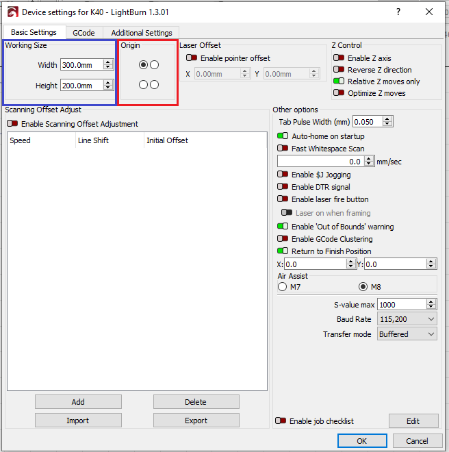
- My default GRBL settings are based on a standard K40 laser, with the standard stepper motors, and standard bed size. You may need to adjust your values to suit your own machine. Research may be needed to get the correct values for your machine’s hardware, however post your questions in the comments section of this writeup, and I, or someone else online may be able to suggest something to help.
- Now that we know the end stops are working (as per PHASE 5 - Testing End Stops), we can test our stepper motor movements. Be sure to have your hand on close to the power switch incase your end stops fail for some reason, or something goes wrong, such that you can switch the machine off as quick as possible as to avoid any damage to your gantry, stepper motors, belts, etc.
- With the K40 powered on, open Lightburn and connect to the machine board, Click on the ‘Move’ tab. Make sure the ‘Distance’ setting is no more than say 20mm, and the speed is no more than 50mm/s – JUST FOR TESTING incase something goes wrong. Jog your laser head X side to side, taking note of the direction the X carriage is moving. Is it moving the correct way? If it is, great, then test the Y axis. If not, you need to invert the direction of the axis using GRBL commands. The easiest way to do this is by using Lightburn, as it handles the mask configuration values for you. While you have Lightburn open, simply click Edit -> Machine Settings and find the ‘Invert X axis direction’ or ‘Invert Y axis direction’ switches, turning them on and off as needed. Make sure you’re inverting the direction. The respective GRBL configuration value is ‘$3 Direction port invert mask.’
- Now that you’ve got the jogging movement working correctly, we need to go to the next phase of testing the `homing sequence`.
PHASE 6 – Testing the Homing Sequence
- Note: Be sure again to be near the power switch on the laser panel when testing this sequence, as the direction may be impacted differently to the jogging feature above.
- In my default K40 GRBL configuration file, I’ve enabled the homing sequence. In lightburn you can click the ‘Home’ button under the ‘Laser’ section on the right hand side. Alternatively, you can also do this by sending the GRBL command $H to the board by using the console.
- Does your machine home at the correct location (top left?). If not, take note of each axis direction when its doing the homing sequence. Is X axis (left to right) homing to the left correctly? If not, you need to invert the homing direction of the X axis – it is a specific configuration value for homing sequence only. This can be changed using Lightburn’s ‘Machine Settings’ panel. The respective GRBL configuration item is $23 - Homing dir invert, mask. Please note that this is different from the Direction port invert, mask, which is $3. It is much easier however to edit these values using Lightburn as it handles the mask values for us. Simply find the ‘Invert X homing direction’ switch and toggle it. Same goes for the homing direction of the Y axis (back and forward). It is independent of the X homing direction, for example, it is possible to have X axis homing correctly and Y not, or vice versa, which is simply fixed by inverting that individual axis homing direction setting.
PHASE 7 – Testing the coordinate system
- In my default K40 GRBL firmware compile, I set the flag HOMING_FORCE_SET_ORIGIN. What this does is set your home position as 0,0 which is what we expect with a 3d printer or desktop laser, otherwise our homing position is set to negative space and requires all sorts of offset configuration in Lightburn, which we really do not need.
- Taken from the firmware source code:
// After homing, Grbl will set by default
the entire machine space into negative space, as is typical
// for professional CNC machines,
regardless of where the limit switches are located. Uncomment this
// define to force Grbl to always set the
machine origin at the homed location despite switch orientation.

#define
HOMING_FORCE_SET_ORIGIN // Uncomment to
enable.
- So essentially, once we hit the ‘Home’ button, and the K40 drives the gantry to the end stops, and the end stops activate, the homing sequence is complete, and the coordinates of the gantry are set to 0,0.
- To test this, simply ‘Home’ your K40 using Lightburn, then draw a circle or a square in Lightburn, taking note of the location you’ve placed it – note, you can simply drag it around on your on-screen laser bed.
- Once you’ve drawn your shape, select it, then click the ‘crosshair’ button on the top toolbar, and you’ll see the following menu displayed:
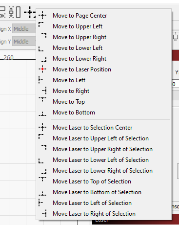
- What I like to do is select ‘Move Laser to Selection Center’, and note where the gantry moves to. Is it in the correct spot? If so, great! If not, we need to troubleshoot, which will be included at a later date.
- Another way to test the coordinate system, is to click the ‘Set laser position’ icon, as shown in the image below.
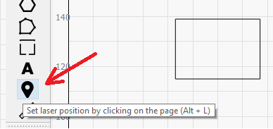
- Once you have this selected, you can simply click your mouse anywhere on your on-screen laser bed and the gantry should move to the location you’ve clicked. Cool huh? 😊
PHASE 8 – Wiring up the PWM Laser On control pin (‘L’ pin on your K40 power supply) DO THIS LAST FOR SAFETY, Just before PHASE 9. Also have your laser powered off, unplugged, etc.
- You need to use a single wire that goes from the K40 Laser power Supply ‘L’ pin (which can vary depending on the K40 power supply, but the pinouts are easily obtainable online, and I’ll try to include some in this writing). This wire plugs into the ‘Digital 8 Pin’ on the RAMPS board (if you were using the RAMPS board in a 3D printer, it is the heatbed port, but its repurposed as a pwm timer in GRBL for RAMPS). This wire controls the ‘pulse width modulation’ (or laser on and off time).
PHASE 9 – Testing the Laser PWM
- NOTE – Whenever we work with lasers we must exercise SAFETY FIRST. Safety, Safety, Safety. These laser tubes utilize incredibly lethal voltage levels. They also emit a laserbeam that could severely injure you or others, even causing blindness. The beam is invisible – that means, you CANNOT SEE IT. Don’t try to look at it, Don’t try to look for it.
- This step should only be completed by someone who is competent with laser equipment, understands how it works, understands the laser high voltages, etc. I take absolutely no responsibility for any injury, death, or any other outcome of performing this upgrade or any of these tests. EXERCISE CAUTION AT ALL TIMES.
- Now that the warnings are out of the way, we need to set the potentiometer on your K40 laser to the level that you’re comfortable with driving your laser tube to AS A MAXIMUM. For example, I run my K40 no higher than 12mA, so I set my potentiometer dial to 12mA. To do this, I enable my laser switch, and turn my potentiometer clockwise at small intervals, tapping the ‘Laser Fire’ button on the K40 user panel and checking my mA gauge while its firing – until it gets to 12mA. I then leave it there at all times, as Lightburn now controls your power levels, not the potentiometer. All the potentiometer needs to be responsible for now, is setting the laser’s maximum safe mA firing value.
- Using Lightburn to test PWM is simple. We’re just trying to establish that our laser powers on and off as expected using the Pulse Width Modulation timer calibrated on the RAMPS 1.4 board.
- Simply draw some shapes in Lightburn – I’d draw 4 or 5 25mm diameter circles side by side, like in the diagram below:

- Now this writeup is not a tutorial for Lightburn – I can do that separately. However you simply change each of these circles to different ‘layers’ in lightburn and this you’re able to set individual power, speed and function settings for each of them separately. For example:

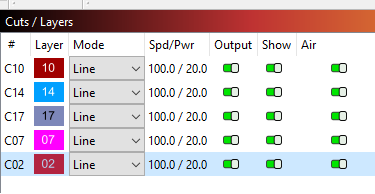
- And then change each of them to do different levels of power, fill, lines etcetera and ensure that the laser power/engraving strength is adjusted according to the power percentage you set for each of the layers – NOTE, the ‘Pwr’ or ‘Power’ level is a percentage value – it is a percentage of the maximum power that you set on your K40 using your potentiometer. For example:
- I set my
potentiometer to 12mA, that is my MAXIMUM power I’d ever like my laser tube to
run at, this limits it safely in hardware.
If I wanted to perform a function in lightburn using the whole 12mA, I
would set my ‘Power’ level on that layer to 100%. Because the Power Level is a percentage of my
maximum set power of 12mA, 100% is 12mA.
And thus, power level of 50% would be 6mA, 25% would be 3mA, etc and so forth.
- I set my
potentiometer to 12mA, that is my MAXIMUM power I’d ever like my laser tube to
run at, this limits it safely in hardware.
If I wanted to perform a function in lightburn using the whole 12mA, I
would set my ‘Power’ level on that layer to 100%. Because the Power Level is a percentage of my
maximum set power of 12mA, 100% is 12mA.
Is your k40 engraving/cutting according to your power and speed settings in lightburn? If so, great, if not, we need to troubleshoot
which I will get to later.